25+ state diagram example in software engineering
State Transition Diagram with example in software engineering Activity diagram explained in the next chapter. Software Design and Project Management.
How To Simplify A Complex And Frustrating Change Management Process When Delivering Software To Production Quora
Video created by The Hong Kong University of Science and Technology for the course Software Engineering.

. State transition diagram software engineeringAdvanced Software Engineering - State Diagrams and State Charts State Transition Diagram Example - Georgia Tech - Software Development. What is state machine diagram with examples. Degree of a relationship set.
This diagram helps us in representing how an object goes through from one state to other and what are the factors which make the object to transit from one state to other. A state diagram shows the behavior of classes in response to external stimuli. Software Development area of ConceptDraw Solution Park provides 5 solutions.
A state diagram is a type of diagram used in computer science and related fields to describe the behavior of systems. Ad Browse Discover Thousands of Computers Internet Book Titles for Less. Class package object use case sequence collaboration component state machine timing interaction overview composite structure.
In this module you will learn. A sequence diagram is a type of interaction diagram because it describes howand in what ordera group of objects works together. These diagrams are used by software developers.
State Transition Diagram with example in software engineering. UML Diagram UML defines 13 types of diagrams. What is a state diagram in software engineering.
A state machine diagram models the behaviour of a single object specifying the sequence of events that an object goes through during its. Define the structure of a software system by describing the system classes their attributes and the relationships among them. Specifically a state diagram describes the behavior of a single object in response to a series of events in a system.
ConceptDraw DIAGRAM is a powerful tool for business and technical diagramming. The three most common relationships in E-R models are. The number of participating entities in a relationship describes the degree of the relationship.
UML Class Diagram in Software Engineering.

An Overview Of Global Humanitarian Response 2014 Humanitarian Data Visualization Infographic No Response

Pin On Tumblr Stickers

15 Best Power Bi Dashboard Examples Rigorous Themes Dashboard Examples Data Visualization Tools Power

Digispark Pro Tiny Arduino Ready Mobile Usb Dev Board Modelisme Naval Projets Arduino Arduino

Benefits Of Transport Management System Tms Transportation Logistics Management Logistics Transportation

Pin On Excel Template

Entity Relationship In A Hotel Management System Hotel Management Relationship Diagram Database Management System

The Trend Of Telecommuting And Its Implication In Workplace Telecommute Infographic Workplace
.webp)
J7dx0zzyrnsham

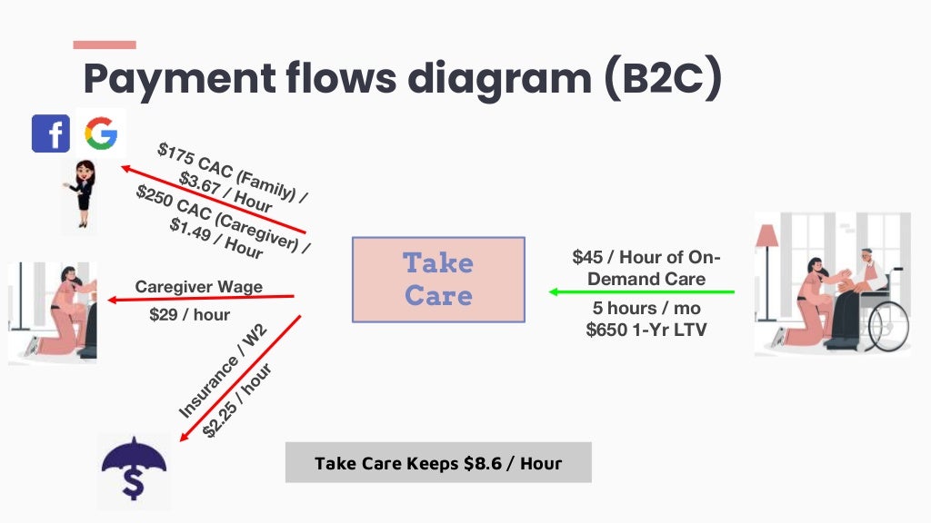
Payment Flows Diagram B2c Take

The Charming Daily Status Report Template Software Testing 15 Things Within Testing Daily Status Progress Report Template Project Status Report Report Template

Top 25 Microservices Interview Questions And Answers

Blank Flow Chart Template For Word New 17 Sample Organizational Chart Templates Pdf Word Excel Organizational Chart Org Chart Flow Chart Template

A Complete Guide To Box Plots Tutorial By Chartio

Pin On Charts

Pin On Charts

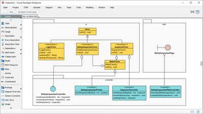
Visual Paradigm Alternatives 25 Diagram Editors And Uml Modeling Tools Alternativeto